
New two-phase system for chip cooling could reduce short-circuit risks
Researchers at Peking University in China have developed an embedded cooling system that uses an...
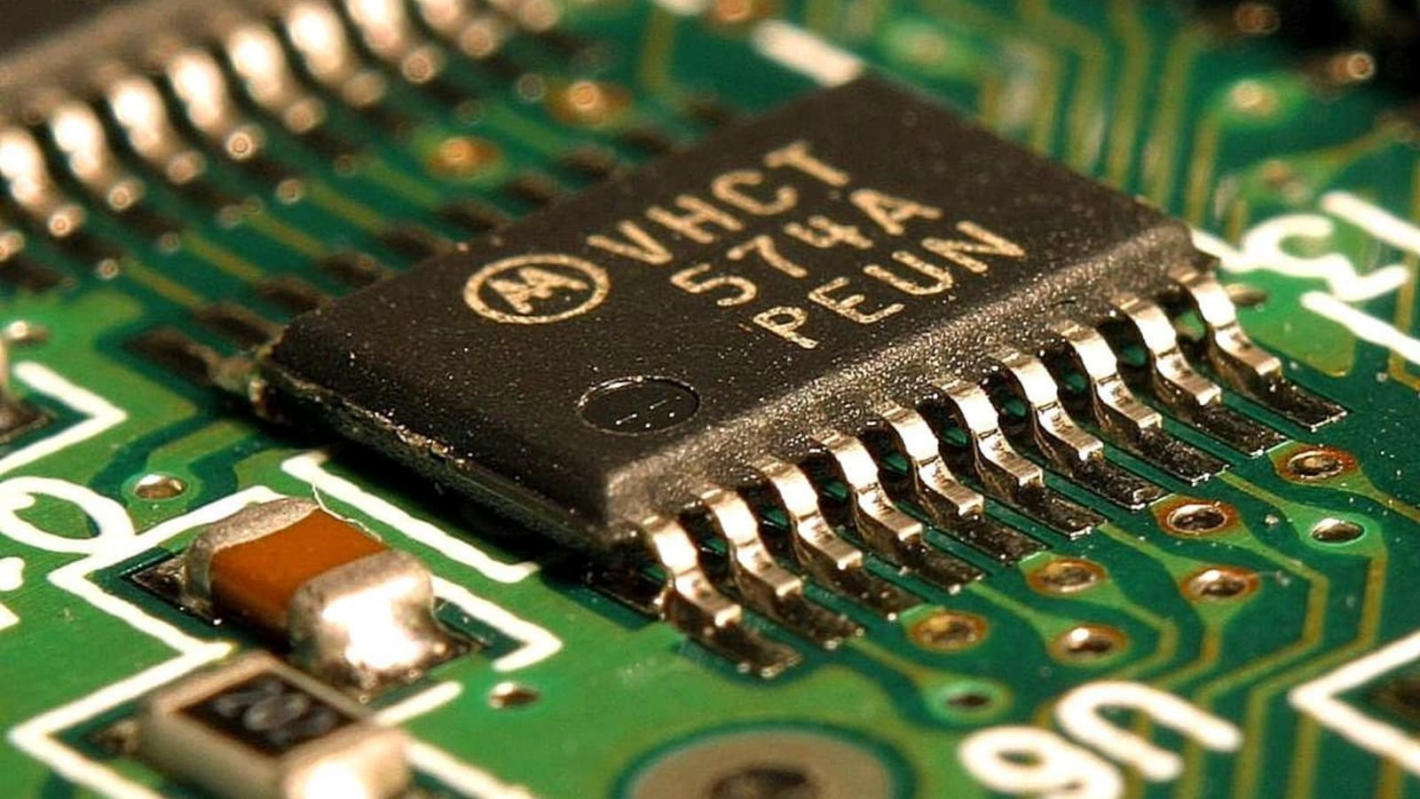
Researchers at Peking University in China have developed an embedded cooling system that uses an electrically insulating liquid to remove heat from electronic chips. It reaches a critical heat flux of 1,570 watts per square centimeter in initial tests.
The design places tiny coolant channels close to heated regions inside the chip substrate. As the fluid passes through these channels, it absorbs heat and partly turns into vapor, which exits through specially arranged outlets.
Bringing coolant closer to chip hotspots
Integrated circuits contain interconnected components that process information or control electrical signals. Their operation generates heat, making effective cooling important for both performance and reliable operation over time.
Embedded cooling tackles this problem by carving microscopic channels directly into the material supporting the circuits. This brings coolant close to the locations where heat is concentrated, allowing the fluid to absorb and carry it away.
Water offers useful thermal properties, but its potential electrical conductivity requires precautions to protect chip components.
“Embedded cooling—where microfluidic structures are directly etched into the chip substrate to send liquid coolants close to the hot spots—can offer dissipation of heat fluxes up to 3,000 W cm−2 using water as the coolant,” wrote Wei Xiao, Zhihu Wu, and their colleagues.
The team instead used HFE-7100, a dielectric coolant, and designed its system around the fluid’s transition from liquid to vapor.
Separate pathways for liquid and vapor
The researchers fabricated their cooling structure using techniques widely used in electronics manufacturing. Alongside channels near the heated regions of test chips, they created a manifold to distribute incoming coolant and collect fluid leaving the channels.
The arrangement combines horizontal inlets with vertical outlets. Fresh liquid enters horizontally to replenish coolant, while the vertical pathways help vapor escape.
HFE-7100 absorbs heat as it boils inside the channels. The resulting heated liquid–gas mixture then leaves through the outlets, carrying energy away from the chip.
“Central to the enhanced heat transfer is the engineering of the horizontal-up manifold, which features horizontal inlets to facilitate liquid replenishment and vertical outlets to accelerate vapor evacuation,” wrote the authors.
Testing the limits of dielectric cooling
Initial tests recorded a critical heat flux of 1,570 watts per square centimeter. This marks the threshold beyond which boiling no longer provides effective cooling.
The figure describes heat transfer per unit area, rather than the total heat removed from an entire chip.
The authors reported that earlier dielectric cooling techniques were often limited to below 1,000 watts per square centimeter, even with pre-cooling and pre-pressurization.
“Because our approach uses microelectromechanical systems technology, it can be directly integrated with standard semiconductor processes and scaled for future electronics,” wrote the researchers.
Further testing on commercially available devices and over longer periods is needed to establish performance and reliability. Those experiments could clarify how effectively the design handles heat in practical electronic systems.
Dielectric fluids reduce short-circuit risks, although their cooling performance is typically lower.
Published in Nature Electronics, the work addresses a trade-off in chip cooling. Water removes heat effectively, but dissolved impurities can make it electrically conductive.
Related articles

Epic shifts to ‘AI-accelerated development’ for upcoming Disney game
Epic Games plans to use AI to generate code and art for an unannounced Disney game, which is now delayed from its original March release window, according to a report from Bloomberg.

Here are all the new HomePod Mini 2 colors
Apple's HomePod Mini 2 is here, and we've gotten a close-up look at the second-gen smart speaker.

DLSS 5 gets toned down for its Hogwarts Legacy debut next month
When Nvidia originally showed off DLSS 5 earlier this year, the technology immediately got branded as gen AI for video games. To gamers, Nvidia had lost the plot.

Apple’s HomePod Mini 2 is available to preorder
After nearly six years, Apple debuted a new, improved HomePod Mini. The $149 HomePod Mini 2 will launch on Friday, October 30th, and you can place a preorder now through Apple.
Old smartphone, new legs: UCLA’s open-source PhoneBot walks on a $400 robot body
Old Android phones gathering dust in drawers could soon have a second career as the...
Paper mill waste could become key material for cheaper sodium-ion batteries
Researchers may have found an unexpected battery material solution within the discarded wood industry byproduct....